
This post delves into the operational principles and comparative analysis of the main data acquisition methods for point cloud data: LiDAR, Photogrammetry, and Structured Light Scanning. Understanding the mechanics behind each method illuminates their respective advantages, limitations, and best use cases.
This is the second part of the Point Cloud Fundamentals topic in Deep Learning Techniques in Point Clouds Series. See Understanding the Nature of Point Cloud Data, and Role of SLAM Algorithm in LiDAR for other parts of this topic!
LiDAR (Light Detection and Ranging)
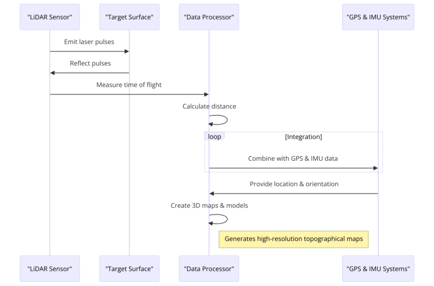
LiDAR works by emitting laser pulses toward a target surface and measuring the time it takes for each pulse to bounce back to the sensor. This time, known as the time of flight, is used to calculate the distance between the LiDAR system and the target based on the speed of light. By sending out thousands to millions of pulses per second and capturing their reflections, LiDAR systems can create detailed three-dimensional maps of the environment. The integration of these distance measurements with the precise location and orientation data from GPS and IMU (Inertial Measurement Unit) systems allows for the generation of accurate and high-resolution topographical maps and 3D models of objects and landscapes.
Advantages
- High accuracy and precision in distance measurement.
- Capable of penetrating vegetation, making it ideal for capturing the ground surface under the forest canopy.
- Effective in various lighting conditions and can operate in the dark.
Limitations
- Relatively high cost compared to other data acquisition methods.
- Requires complex processing and analysis techniques.
Applications
- Topographic surveys
- Forest inventory and management
- Urban planning and infrastructure development
- Coastal zone mapping
Photogrammetry (Image-based)
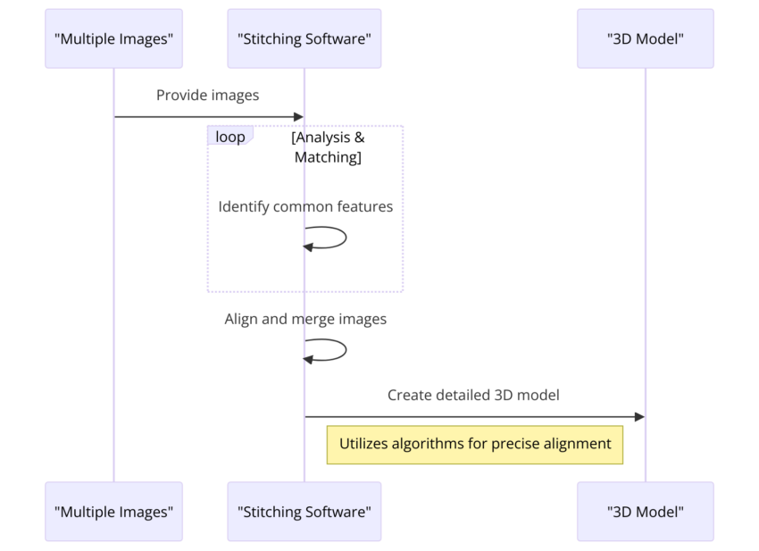
Photogrammetry is a technique that uses photography to measure and map environments and objects. It captures multiple overlapping images from different viewpoints, typically using cameras mounted on aircraft, drones, or handheld devices. Sophisticated software then analyzes these images to identify common points across the overlapping areas, using the principles of stereo vision to infer depth and calculate distances. This process generates detailed 3D models or maps of the photographed area. The accuracy and resolution of the models produced by photogrammetry depend on the quality and resolution of the images, as well as the precision of the camera’s positioning information. Photogrammetry is widely used in fields such as surveying, architecture, engineering, and archaeology, offering a cost-effective and versatile method for creating high-resolution maps and 3D models of both natural landscapes and man-made structures.
Advantages
- Cost-effective and versatile.
- High-resolution imagery can provide detailed surface textures.
- Suitable for a wide range of applications, from small objects to large landscapes.
Limitations
- Dependent on lighting conditions and weather, which can affect data quality.
- Requires overlapping images for accurate 3D reconstruction, which can be time-consuming to capture.
Applications
- Archaeological site documentation
- Environmental monitoring and conservation
- Urban planning and real estate
- Cultural heritage documentation and digital preservation
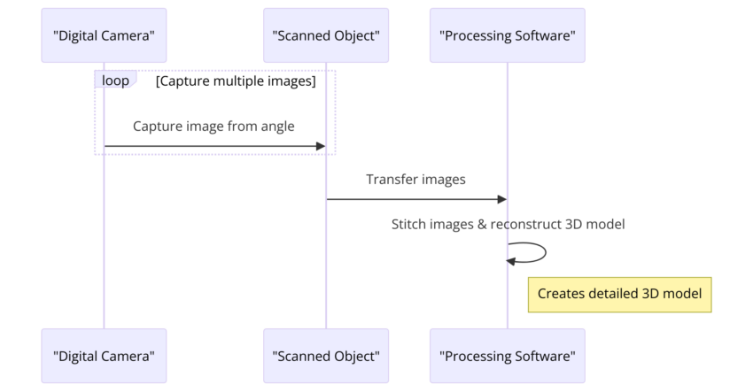
The sequence diagram in Fig 2 for the photogrammetry process, an image-based 3D scanning method, features three key components: the Digital Camera, the Scanned Object, and the Processing Software.
The process begins with the Digital Camera taking multiple images of the Scanned Object from various angles. This step is crucial for capturing the complete geometry and texture of the object. These images are then transferred to the Processing Software, which performs the next critical step: stitching these images together and reconstructing a detailed 3D model of the object.
The diagram emphasizes the iterative nature of capturing images from multiple perspectives, which is fundamental to photogrammetry, allowing for the comprehensive digital representation of the object in three dimensions. This method leverages the overlap between images to deduce depth and geometry, resulting in a highly detailed and accurate 3D model.
Structured Light (3D Scanning)
Structured light 3D scanning is a method that captures the three-dimensional shape of objects by projecting a specific light pattern onto the subject and analyzing how the pattern deforms upon contact with the object’s surface. This technique involves using a camera and a light source, such as a laser or LED projector, which emits a known pattern (e.g., lines, grids, or dots) onto the object. The camera, positioned at a known angle relative to the projector, captures the distorted pattern.
The core principle behind structured light scanning is triangulation, where the angle and distance between the camera and projector, along with the pattern’s deformation, are used to calculate the 3D coordinates of the object’s surface points. By moving the light pattern across the object and capturing multiple images from different angles, the system can compile a highly detailed and accurate 3D model of the object.
Structured light scanning excels in capturing the fine details of objects, making it highly effective for applications that require precise models, such as quality control in manufacturing, reverse engineering, and digital preservation of cultural artifacts. This method is particularly useful for scanning small to medium-sized objects and can achieve high levels of detail and accuracy. However, its effectiveness can be influenced by the object’s surface properties; for example, shiny, reflective, or transparent surfaces can pose challenges and may require special preparation to ensure accurate scanning.
Compared to other 3D scanning technologies, structured light scanning offers a balance between speed, accuracy, and resolution. It is faster than point-by-point laser scanning and can achieve finer detail over larger volumes than photogrammetry, without the need for extensive post-processing. However, it typically requires a controlled environment to minimize interference from ambient light and ensure the integrity of the projected pattern.
Advantages
- High precision in capturing the 3D shape of objects, even with complex geometries.
- Fast data acquisition time.
- Suitable for indoor use and capturing small to medium-sized objects.
Limitations
- Limited to relatively small areas or objects compared to LiDAR and photogrammetry.
- Performance can be affected by ambient light conditions and the surface properties of the object.
Applications
- Industrial design and manufacturing
- Heritage preservation
- Medical modeling and prosthetics design
- Quality control and inspection
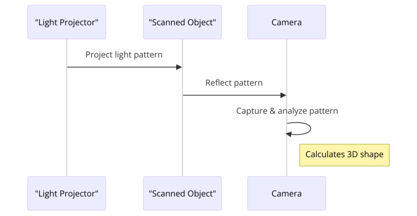
The simplified sequence diagram for structured light 3D scanning consists of three primary components: the Light Projector, the Scanned Object, and the Camera. The process begins with the Light Projector emitting a specific light pattern onto the Scanned Object. This pattern could be lines, grids, or dots, which then gets reflected off the object’s surface. The Camera captures this reflected pattern and proceeds to capture and analyze the distortion of the light pattern caused by the object’s three-dimensional shape. Based on this analysis, the Camera calculates the 3D coordinates of the object’s surface, effectively determining its shape. This simplified process illustrates the fundamental operations involved in structured light 3D scanning, emphasizing the projection, reflection, and capture/analysis stages essential for calculating the 3D shape of the scanned object.
Comparative Analysis
Choosing the appropriate data acquisition method depends on several factors, including the level of detail required, the environment of the application, and budget constraints. LiDAR offers unparalleled accuracy and penetration capabilities, ideal for dense environments and large-scale surveys. Photogrammetry is more accessible and flexible, favored for projects requiring high-resolution imagery on a smaller budget. Structured Light provides exceptional precision in controlled settings, perfect for industrial applications and historical preservation.